IMSAI CP-A

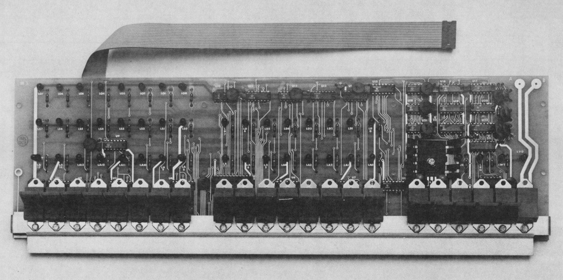
The CP-A board is the operator's panel for the IMSAI 8080 System. It includes operator switches, indicator lights and all logic necessary to operate the IMSAI 8080 System.
- Contents
Visit our Facebook group for announcements, discussions, and more information about supporting the IMSAI CP-A.
We put a lot of time into creating, gathering, and organizing the information in this page.
If you found any of this to be useful to you, especially if it helped you to make or save money,
please
to help us continue making content like this available.
Over the past 20 or more years, much effort has been made by numerous individuals to source the iconic paddle switches which went out of production in the late 1990s.
This guide is helpful to find new old stock switches, but it is also helpful if you are mixing and matching switch frames and actuators.
If you are adventuresome enough to print your own actuators, you still need to know what switch and frame to start with.
We’ll even help you source new alternative switches.
Let’s start at the beginning with the original IMSAI CP-A switches.
The following table shows the original IMSAI CP-A switch cross-reference and BOM.
| Qty |
IMSAI P/N |
C&K P/N |
Description |
| 8 |
26-1500001 |
7101J47 |
Blue Paddle Switch, on/none/on |
| 8 |
26-1500002 |
7101J43 |
Red Paddle Switch, on/none/on |
| 2 |
26-1500003 |
7105J47 |
Red Paddle Switch, momentary |
| 3 |
26-1500004 |
7105J43 |
Blue Paddle Switch, momentary |
| 1 |
26-1600001 |
7101J33 |
Red Rocker Switch, on/none/on |
The C&K part numbers in the table are most likely the ones as ordered by IMSAI purchasing.
They are very simple part numbers that specify the switch configuration, the actuator type, and the color.
Everything else is default.
This is based on forensic analysis of original IMSAI switches and examining C&K catalogs from 1986, 1987, and 1993.
The 1986 catalog was most helpful as it best explained what the default options were closest to the time IMSAI was producing the CP-A.
If you are searching for old stock of these switches, try adding Z, ZQ, or ZQI before the last digit to find the exact switches IMSAI used.
For example, 7101J4ZQI7.
Seeing how unlikely it is that you will find these exact switches these days, let’s discuss options.
While the 7101 and 7105 model numbers cannot be changed, the rest of the options are somewhat negotiable.
Actuator
The actuator is a major part of the iconic look of the IMSAI 8080 system. The IMSAI CP-A used a J3 rocker and J4 paddles.
The J3 is the only actuator currently in production.
The following table shows the actuator options that are all interchangeable with each other.
If you are willing to make a statement, some of the alternative paddles might be an option for you.
| Option |
Description |
Comments |
| J3 |
Rocker |
Used in the CP-A power switch. |
| J4 |
Paddle |
Used in the CP-A for all except the power switch. |
| J5 |
Tapered paddle |
Might make an interesting alternative look. |
| J10 |
Large rocker |
Unsuitable for use in the CP-A, but the switch and bracket are compatible with J4 or J5 actuators
in momentary-only applications. |
| J47 |
Paddle |
Identical to the J4, but the switch bracket is incompatible with the CP-A.
You might be able to harvest the actuators from a switch to use on an existing switch, or a switch with the wrong color actuator. |
| J57 |
Paddle |
Identical to the J5, but the switch bracket is incompatible with the CP-A.
You might be able to harvest the actuators from a switch to use on an existing switch, or a switch with the wrong color actuator. |
The following table shows the actuator colors. Black is the default if not specified in the part number.
Some of the colors are somewhat unique to C&K and other manufacturers such as NKK’s “equivalent” colors will be off.
| Option |
Color |
| 1 |
White |
| 2 |
Black |
| 3 |
Red |
| 4 |
Orange |
| 5 |
Yellow |
| 6 |
Green |
| 7 |
Blue |
| 8 |
Brown |
| 9 |
Gray |
While the IMSAI colors are red/blue, there are other contemporary color combinations that might be cool if you can find them:
white/black, white/gray, black/gray. All one color is another option. Just about any combination of red, orange, yellow, and
brown would give it a definite ’70s feel.
Termination
The termination option is somewhat flexible if you bear in mind that the CP-A switch mounting holes are drilled for the larger Z terminals.
The following options should work but would require assembly precision to align the switches: Z3, C, W, W1, W2, W3, W4, W5.
Be advised that all except the C option will include epoxy sealing by default; read the paragraph on terminal sealing for cautions.
Most of these options will also require the terminal leads to be trimmed after soldering.
Contact Material
The 40+ year old switches we have as reference show the telltale black tarnishing on the terminal silver plating.
After the IMSAI CP-A production runs were over, C&K added contact material options that continue to the present.
The following table shows the available contact material options and how they apply to the CP-A.
| Option |
Description |
Comments |
| B or K¹ |
Contacts & Terminals: Brass, with gold plate over nickel plate.
Rating: ≤ 0.4VA @ ≤ 20VAC/DC. (Std. with all termination options except Z, C, Z3) |
Best for all except the power switch. |
| Q or M¹ |
End Contacts: Coin silver, silver plated.
Center Contact & All Terminals: Brass, silver plated.
Rating: 5A @ 120VAC or 28VDC; 2A @ 250VAC. (Std. with termination options Z, C, Z3) |
All CP-A switches use this option. A good choice for the power switch, a poor choice for all others. |
| G or L¹ |
End Contacts: Coin silver, with gold plate over nickel plate.
Center Contact & All Terminals: Brass, with gold plate over nickel plate.
Rating: ≤ 0.4VA @ ≤ 20VAC/DC or 5A @ 120VAC or 28VDC; 2A @ 250VAC. |
Best of both worlds.
When used as a power switch, the gold flashing burns off and it functions as a silver contact switch. |
¹ These options have the same contact material. The terminals are copper alloy, with tin-lead alloy over nickel plate.
Terminal Sealing
The IMSAI switches were unsealed. While this might not seem to be the best choice at first glance, it is what the CP-A was designed for.
| Option |
Description |
Comments |
| (None) |
No seal. Std. with Z, C terminations, not avail. with all other terminations. |
Original IMSAI specification. |
| E |
Epoxy seal. Std. with Z3, W-W5, A, AV2, V3-V9 terminations. |
Might interfere with proper mounting of the switch onto the circuit board. |
| I |
No seal for 71xx switches. Available only with Z, C, Z3 or W-W5 terminations. |
Used to override the default epoxy seal with Z, C, Z3 or W-W5 terminations. |
Here is an excerpt from the IMSAI CP-A manual regarding the soldering of switches:
When the entire row has been spaced accurately, the board should be turned over and a center switch should be soldered in place taking care that the board is not bowed towards or away from the switches. When the board is positioned correctly, there will be a small space approximately ³⁄₆₄ inch or slightly under ⅟₁₆ inch between the bottom of the switch and the front of the front panel board. The two end switches should be similarly checked to make sure that the spacing to the board is correct and soldered in place, and then one switch each at the ¼ positions checked as to spacing from the board and soldered into place.
Then the remainder of the switches can be soldered. Examine visually for solder splash or bent/unsoldered pins.
It’s probably fair to say that the expected gap between the circuit board and the bottom of the switch is about 0.05 inch.
This is less than the 0.075 inch max depth of the epoxy seal.
This means that if you choose switches with the E option, you may have to remove some of the epoxy sealant to get the
switches to seat properly on the circuit board.
As it turns out, C&K is currently producing (as of 2022) the 7101 and 7105 switches with the black J3 rocker actuator.
Unfortunately the J4 paddle actuator has been discontinued.
If you can find other switches with the J4 paddle (or print some), you can swap out the J4 for the J3.
NKK currently manufactures compatible switches to the old C&K line that appear to be better switches.
The switches are the M series.
M2012TY (now MN12TY) replaces the 7101. M2018TY (now MN18TY) replaces the 7105. The next letter of the part number is the contact material.
| Option |
Description |
Comments |
| G |
Gold; Rated 0.4VA max @ 28V AC/DC max |
Similar to C&K B. Best for all except the power switch. |
| W |
Silver; Rated 6A @ 125VAC and 3A @ 250VAC. |
Similar to C&K Q (default). A good choice for the power switch. |
| A |
Gold over Silver; Rated 6A @ 125VAC & 0.4VA max @ 28V AC/DC max |
Best of both worlds. When used as a power switch, the gold flashing burns off and it functions as a silver contact switch. |
The next two digits are the terminal code. The solder lug (01) is identical to the C&K Z terminal used in the CP-A,
but the Straight PC (03) should also work with some additional assembly care.
If you order a switch with just the above information, it will come without a rocker or paddle.
You can order them separately (see below). If you want the rocker, add a -J and a color code.
To order a paddle, add a -H and a color code.
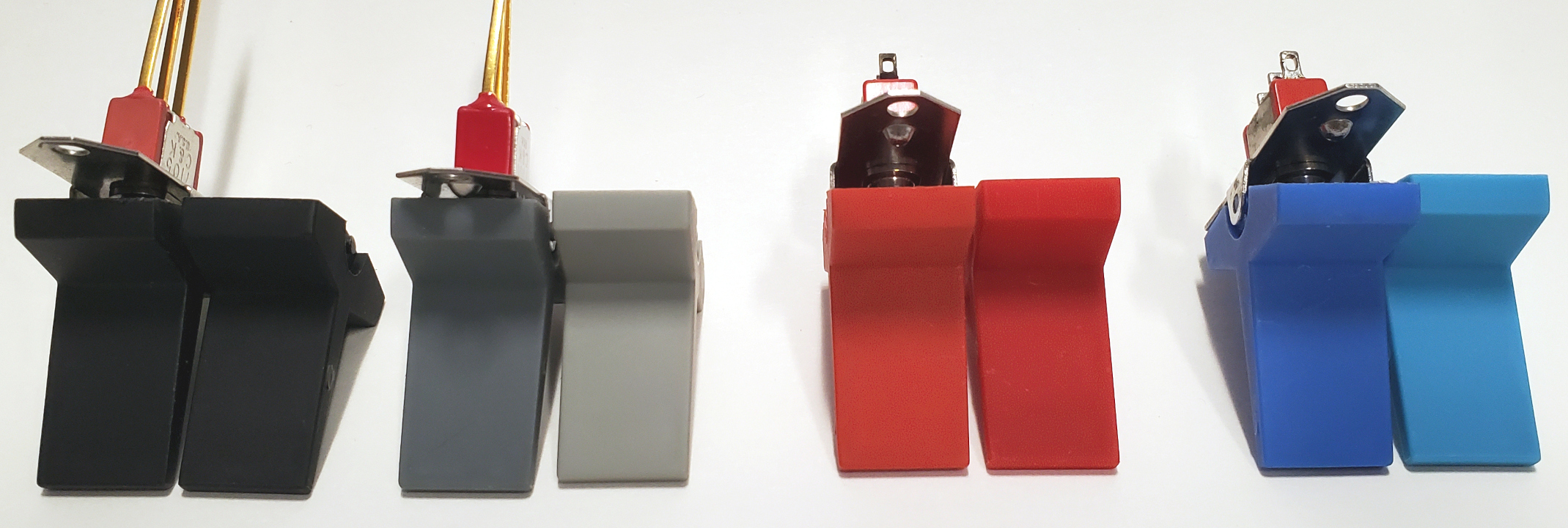 The picture to the right shows the actuator colors.
In each group, the C&K is on the left. Note that we have only compared the black, gray, red, and blue colors with the C&K.
We do not have white, yellow, or green C&K actuators for reference. C&K orange and brown are not available in the NKK line.
So much for the 1970s! The picture to the right shows the actuator colors.
In each group, the C&K is on the left. Note that we have only compared the black, gray, red, and blue colors with the C&K.
We do not have white, yellow, or green C&K actuators for reference. C&K orange and brown are not available in the NKK line.
So much for the 1970s!
The following table lists the NKK color options and how they compare with the C&K colors.
| Option |
Color |
Comments |
| A |
Black |
A tiny bit darker than the C&K. Nearly identical. |
| B |
White |
We have not compared to C&K white. |
| C |
Red |
A little darker than the C&K. |
| E |
Yellow |
We have not compared to C&K yellow. |
| F |
Green |
We have not compared to C&K green. |
| G |
Blue |
Much lighter than the C&K. |
| H |
Gray |
Much lighter than the C&K. Has almost a yellow-green hue. |
If you want just the paddles, Mouser has a few as of May, 2022. The part number is AT4156 for the rocker and AT4157 for the paddle,
and uses the same color chart as the switches.
They fit either the NKK or the C&K switch base.
Our advice is that, aside from the black, the colors are too far apart between the NKK and C&K to mix in close proximity.
The LEDs used in the original CP-A were manufactured using the GaAsP (Gallium Arsenic Phosphide) process,
which had some rather distinctive characteristics by today’s standards.
This makes sourcing replacement LEDs difficult if you’re trying to match existing ones.
Well, whatya know... I was going through my 1,000 databook collection and opened the Fairchild Optoelectronics Data Book [1978]. Lo and behold, I found the package outline Opto-5 which is a perfect match. Going through the Opto-5 offerings, the FLV110 is a perfect match. It lists the following in the cross-reference as direct replacements: Dialight 521-9165, Litronix RL 2, Xciton XC 110 (pin length differences). Here is the datasheet: Fairchild FLV110 (Opto-5).pdf. As of 2024, Rochester Electronics has over 100,000 in stock at $310.66 for 4,309 pieces.
Let's check the cross-reference...
Let’s start with a specification summary. This is based on physical and electrical measurements of NOS IMSAI LEDs.
The optical characteristics are still a bit of work in progress,
as this data is being derived by subjective human comparison to modern LEDs with spec sheets.
| Characteristic |
Value |
Unit |
Comments |
| Body |
|
|
T-1¾ spherical lens with flange, diffused and red tinted. |
| Total body length |
7.3 |
mm |
Measurement from the flat lead entry base to tip of rounded lens. |
| Body diameter |
4.85 |
mm |
|
| Lead spacing |
2.54 |
mm |
Typical for T-1¾. |
| Lead length |
18 |
mm |
Anode, 0.4 mm square lead with no mounting stand-offs. |
| 16.5 |
mm |
Cathode, 0.4 mm square lead with no mounting stand-offs. |
| Forward current |
20 |
mA |
This is the operating current at which the brightness and other characteristics are measured. |
| Forward voltage |
1.7 |
V |
|
| Peak wavelength |
660 |
nm |
Based on typical 1970s GaAsP LED technology and subjective comparison with other known LEDs. |
| Brightness |
TBD |
mcd |
Comparisons to known LEDs is in process, but GaAsP LEDs are typically much less bright than modern processes. |
| Viewing angle |
TBD |
° |
So far seem to be > 30°. |
So, here are the challenges, if you’re trying to match new LEDs to the old IMSAI ones.
Color: At 660 nm, the IMSAI LEDs are a “pure red.”
Most common red LEDs today have a 630 nm peak wavelength and appear ever so slightly orange when viewed side by side with a GaAsP LED.
Brightness: Modern LEDs are typically much more efficient than the older GaAsP LEDs, and have higher forward voltage drop (2 to 3 volts).
This will require adjusting the series current limiting resistors to get close to the IMSAI LED brightness.
The good news is that the forward current will drop dramatically in most cases.
Physical: The IMSAI LEDs are considerably shorter at 7.3 mm than most available today at 8.6mm.
They’re also a tiny bit smaller at 4.85mm, but this is not generally visible.
Trying to get the longer and shorter LEDs to match side-by-side, especially when viewing off-axis will be difficult.
Viewing angle: Replacement LEDs should have as wide a viewing angle as possible.
While the viewing angle of the IMSAI LEDs is not known to any degree of accuracy, subjective comparison of known LEDs suggest that it is greater than 30°.
If you’re building a CP-A or clone from scratch, you have a lot of latitude to choose bright,
efficient LEDs without worrying too much about matching existing ones.
If you’re trying to replace a few LEDs in an existing CP-A, things will be more challenging unless you have a source of the originals.
We have never seen the original IMSAI LEDs available anywhere, even on eBay.
The best you’re going to get is “close,” leaving you with one of two choices −
replacing all of them, or replacing them in groups so the differences will be less noticeable.
As for mounting replacement LEDs, using the original IMSAI assembly instructions with the ⅛"
spacer won’t work because of the new LED’s longer length. Our suggestion is to match the tops of the lenses to each other.
Unless you’re getting NOS IMSAI LEDs, you will almost certainly have to change the series resistors.
If you are getting NOS IMSAI LEDs, please let us know!
We put a lot of time into creating, gathering, and organizing the information in this page.
If you found any of this to be useful to you, especially if it helped you to make or save money,
please
to help us continue making content like this available.
Schematics
Two versions of the CP-A schematic exist. Both contain known errors which were spotted during the drafting of the design phase
of the CP-A Rev. 4A project.
The IMSAI schematic has the following drafting errors:
- The “HOLD” LED (LHD) is incorrectly labeled “LHT.” The PCB legend is correctly labeled “LHD.”
- S3 is missing the “STOP” legend on pin 1.
- U25-5 is incorrectly connected to U15-1 and should connect to U15-2
The Josh Bensadon redraw has the following drafting errors:
- U5 (8212) is missing the connections between pins 1 (DS1), 13 (DS2) and ground.
- In the “HAD” open collector section, SA8 (address switch 8) is incorrectly connected to U4-12. That inverter instance should be pins 10 & 11.
- The “HOLD” LED (LHD) is incorrectly labeled “LHT” (a carry-over from the IMSAI schematic error).
- Near S3 (Run/Stop), R14 and R15 are incorrectly labeled R10 and R11.
- Near S5 (Deposit/Deposit Next), R6 and R7 incorrectly labeled R10 and R11.
Manuals
Modification Articles
Datasheets
|