Parastream’s IMSAI Gen 2 System

Parastream inherited Robert Weatherford’s IMSAI machine when he incorporated Parastream Technologies.
His journey into the world of microcomputers began in 1974 after he read the article in the September 1973 Radio Electronics
and subsequently built the TV Typewriter by Don Lancaster. Robert continues the story here...
INDEX
History of the IMSAI Development Machine
Robert recalls the early evolution of his IMSAI development machine…
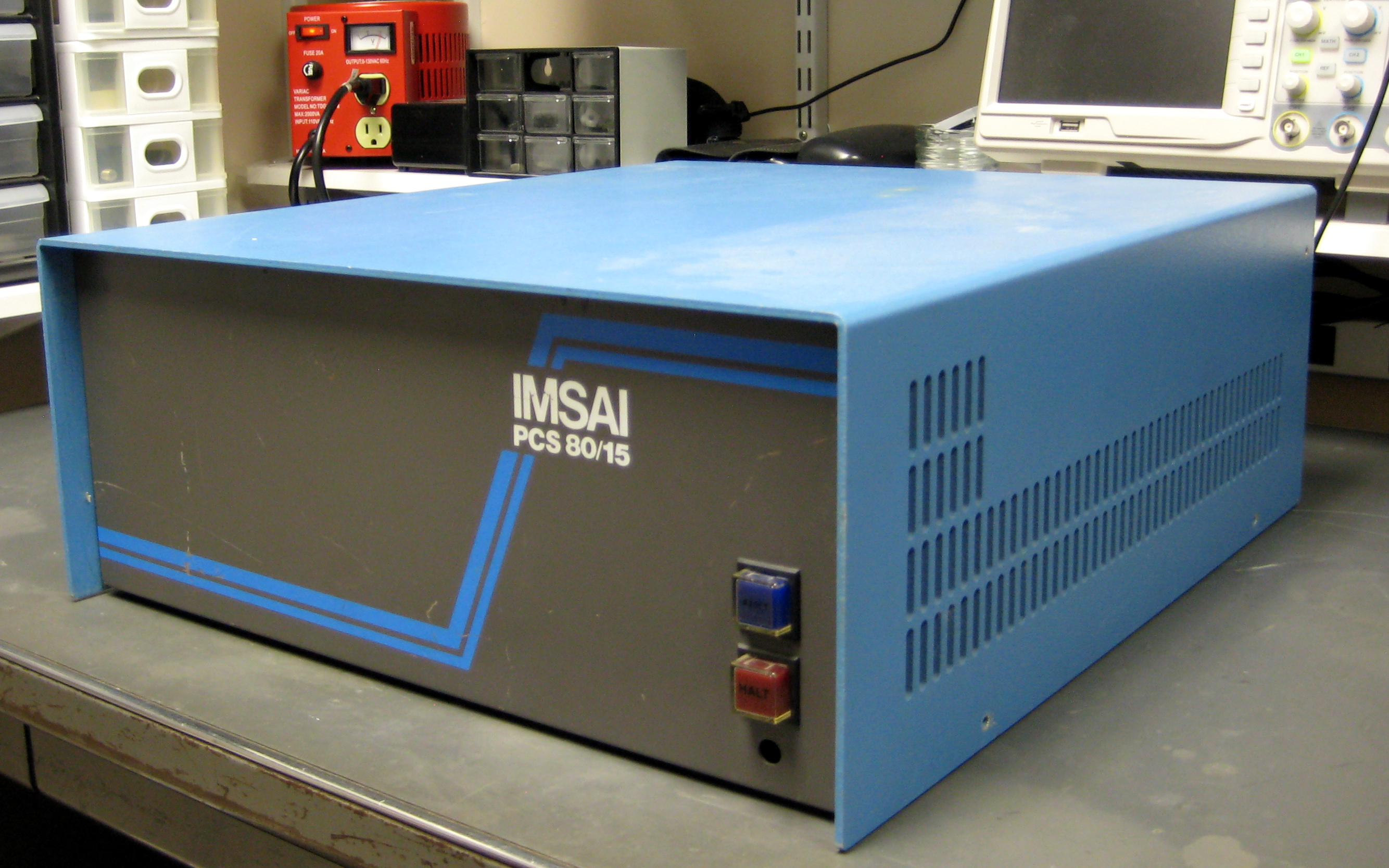
The IMSAI development machine started out as an IMSAI PCS 80/15 with an MPU-B, 64K RAM-III, VIO-D, and a prototype DIO-E.
This was my second IMSAI system. I’m pretty sure I sold the original when I was a cash-strapped musician.
Todd Fischer was able to provide me a suitable new system that just needed a little TLC to become great.
Attached was (probably) a IMSAI IKB-1 keyboard, an Okidata µL92 dot matrix printer, a Ball CRT monitor, a 1200 bps modem
(which had a nifty real-time clock extension), and a dual 8" DSDD cabinet.
It ran IMDOS and CP/M 2.2. This was in early 1984.
Picking up where I left off, and undeterred by the introduction of the IBM PC,
I began designing modifications and upgrades to the now five year old system.
I ran across a Honeywell/Burroughs TP139 keyboard. That thing was a beast.
It came with all the technical specs I needed to design a custom interface for it.
Then I got the idea to actually do something like the IMSAI IMM and create a megabyte micro.
256k DRAMs were available in the same package as the 16k ones used in the RAM-III. Now I needed a bank-switcher.
CP/M 3 had just come out, so I designed the bank switcher around what CP/M 3 wanted.
A new Centronics port for the printer rounded out the design.
And if that wasn’t enough to cram into a single S-100 board, I added a PROM programmer that had programmable timers and an
interface for a never-developed programmer.
Building a programmer was always high on my list (by the way, in 2021, I saw the errors of my ways,
and purchased one for Martin Eberhard’s kits for the 1702A and have put one for everything else in the budget).
I had other designs in mind. Fast Z80 boards. 16-bit 8086 boards, and a DMA controller to streamline the memory moves that
bank-switching requires. Several PALs were designed to build the DMA controller.
Even proposing a revision to the IEEE 696 specification.
Fast forward to today. It’s been over 30 years since I worked on the IMSAI and CP/M 3.
I was ready to write it off as part of the past that was instrumental in getting me to today.
I still had boxes of the old 8" diskettes full of my development work.
In 2008 I imaged all of them, and in late 2020, I wrote a .NET application to read the images and access the CP/M files.
For the first time in over 30 years, I was looking at my old work.
Thanks to the Internet, I have found groups of enthusiasts who are still interested in CP/M and S-100 stuff.
I am now motivated to publish all this stuff for whoever might care while I can still remember some of what I did.
Here was the system configuration when it was retired around 1986:
- IMSAI PCS 80/15 Chassis with PS-28 Power Supply.
- IMSAI MPU-B 8085 processor, overclocked to 5 MHz.
- IMSAI RAM-II, retrofitted with 256k DRAMs for a total of 1MB.
- IMSAI VIO-D, modified for 25-line display.
- IMSAI DIO-E with PDS-II, 8" DSDD controller.
- Proprietary OMNI-1 with Burroughs keyboard, parallel printer, and PROM programmer ports,
and 20-bit extended address generator.
- Burroughs TP139 keyboard.
- Okidata µL92 dot matrix printer.
- Ball CRT monitor.
- Qume 842 dual 8" floppy cabinet.
- ADC 1200 bps modem with RTC.
The 2020 Revival
When we started reviving the machine in 2020, we started on the power supply by replacing the computer-grade electrolytic
capacitors just to be safe. We had a few tantalum tantrums on the Qume 8" drives to take care of.
Unfortunately, the Burroughs keyboard had died.
Several keys had quit working, and there are no hall-effect replacement parts available.
We also found ourselves without a working CRT monitor.
So where do we go from here? We’re going to go through the system, one board at a time, and document the mods that were made,
and in some cases, make some new ones to fit the times.
We are going to have to go back and work through a 9600 bps serial port and terminal software for a while.
The boards are:
- OMNI-1
- EXP-10
- MPU-B
- VIO-D
- RAM-III
- DIO-E
After all this is done, we can get on to publishing the IMDOS, CP/M 2.2, and CP/M 3 BIOS and utilities.
As the work is done, we will update this page.
OMNI-1
The OMNI-1 is a wire-wrapped prototype for the board that has “everything.”
Everything meaning the stuff I needed for my own system. Most of the features in it were never meant for public consumption.
I had acquired a giant Burroughs keyboard with a proprietary serial interface, so the OMNI-1 needed an interface for that.
I always wanted a PROM programmer, so it had programmable timing circuits that an external level-shifting box would use to
make the actual programmer “personality module.” In 2020, the keyboard does not work and is unrepairable.
The PROM programmer interface was and will never be used.
As half the circuitry on the board was dedicated to these two functions, I decided to rip it out to reduce unnecessary
power dissipation.
What’s left? A Centronics parallel printer port and a 20-bit extended address generator.
Both of these are used by bank-switched CP/M 3.
Eventually the printer port will be replaced by a “modern” I/O card and a full 24-bit version of the extended address
generator will be included in a new card design.
The task for the revival are:
- Rip out the PROM programmer and Burroughs keyboard interfaces to reduce heat generation. Done 10/2021.
- Repair the connections to the remaining parts.
EXP-10
- Make sure the terminators are functioning properly and are up to IEEE 696 specs. Done 4/2021.
- The schematic doesn’t seem to exist anywhere, so we may create one. Done 3/2021.
MPU-B
- Create documentation for the Rev 2 boards. Done 3/2021.
- The MPU-B has some undocumented hacks had been done to deal with generating the 2 MHz bus clock and wait states. Undo those. Done 3/2021.
- Create new mods for the bus clock and wait states. Clock done 3/2021. Wait states to do.
- Buffer the SOD signal onto bus pin 66 using U32-6 and 7. This will go away when the IO-21 is done. Done 3/2021.
- Implement the bus clock mod. Done 3/2021.
- Currently the OMNI-1 board is generating the 2 MHz signal; get rid of that. Done 3/2021.
- I removed the 8 data bus pull-ups. Was that necessary and/or a good idea? Replaced 3/2021.
- Look at what I did to J3 and the jumpers. What was that? Removed 3/2021.
VIO-D
- Document the existing 25-line display mods. Done 2/2021.
- Because old analog monitors are hard to come by, design new mods to drive MDA, EGA, and VGA monitors.
- Fix the “snow” and full-screen reverse video issues.
- Create new VIOROM versions to support 25-line modes and enhancements.
- Create new PROM for 25-line refresh address decoding.
- Make sure the VIO drives the PHANTOM* line.
RAM-III
Document the mods to upgrade it from a 64K to a 1MB board. Look after any IEEE 696 issues such as PHANTOM* pin assignment.
DIO-E
Document the mods necessary to convert a DIO-C. Update firmware to handle 2/3MHz processors, plus an additional switch for 4/5MHz processors. Maybe back-port the timing changes to the DIO-C and DIO-D firmware. Look after any IEEE 696 issues such as PHANTOM* pin assignment.
IO-21
(new design!). IBM PC/AT keyboard, PIC, RTC, parallel & async serial port, and speaker board. Make a couple of port assignment and interrupt vector changes to CP/M to accommodate. Rip out parallel port from OMNI-1.
EAG-696
New design! 24-bit extended address generator for the S-100 bus. Make CP/M updates. Remove and retire OMNI-1 from service.
TMA-2
New design! 24-bit 2-channel TMA controller. Moves, compares, and initializes blocks of memory in the 24-bit address space at lighting speed.
The Current State of the IMSAI Development Machine
The EXP-10 motherboard is out of the chassis being worked on.
DIO-E
Not tested.
EXP-10
The EXP-10 has a piezo-electric beeper on bus pin 66. When pin 66 is low, the beeper sounds. This pin is currently driven by the MPU-B SOD signal from the CPU. This will go away when the IO-21 is done. It also has had the 330Ω terminators replaced with two-ended 680Ω resistors.
MPU-B
The MPU-B drives bus pin 66 with a buffered SOD signal from the 8085A using U32-6, 7 after the pSTVAL* mod. The current terminal emulators use this as a Ctrl+G sound. This will go away when the IO-21 is done. VI3* goes to RST 6.5, and NMI* goes to TRAP. The serial port current loop driver U41 has been removed as it is not needed. It also has several mods and upgrades:
- XRDY (3), NMI (12) mod to allow NMI to be used.
- pSTVAL*, INTE, and ERROR* mods.
- S-100 Clock (Pin 49) upgrade.
- Address Line Drive upgrade.
RAM-III
Not tested.
VIO-D
The VIO has the 25-line HD display mods. The VIO is enabled only in the address space 0F000 through 0F7FF. This is done in the OMNI-1 by driving J1-65 high when A16 through A19 are low. The VIO picks up J1-65 and wires it to the M (enable) signal. There appears to be no purpose for this in the system’s current configuration, because the OMNI-1 bank switch common area is set to either E000 through FFFF (“common area”) or F000 through FFFF (“BIOS area”). My best guess as to what I was thinking 35 years ago was that I was designing a memory moving bus master that could copy bytes in and out of the non-zero 64 K banks normally “hidden” behind the common area. The MPU-B and DIO-E had I/O ports to switch them in and out, but not the VIO. If we had used the VIO high addressing feature instead, it would only be enabled at FF000 through FF7FF, and wouldn't be visible after a reset.
The VIO ROM does need to be disabled for Banked CP/M to run, because we need the 2 KiB common address space 0x0F800 through FFFFF for CSEG code.
OMNI-1
In the process of ripping out the PROM programmer and Burroughs keyboard interfaces. The Centronics port and bank-switcher will be left alone.
Bus Signals
The following table lists the bus signal pins that either deviate from the IEEE 696 standard, or have explanatory text.
| Pin |
Name |
Description |
| 66 |
NDEF |
When pin 66 is low, the beeper on the motherboard sounds. |
| 75 |
RESET* |
This signal is not terminated on the motherboard because the MPU-B has its own RC reset circuit that would be upset by a terminator. |
How It All Began All Began
The Microcomputer Beginnings and IMSAI
This is Robert Weatherford’s account of how he wound up at IMSAI. The time frame of the story spans about five years from 1974 to 1979. The names of many persons have been intentionally omitted in cases where I have not gotten their permission. The names that do appear are already public names on the Internet.
In 1973, I had recently moved to the city of Belmont in the San Francisco Bay Area from Flanders, NJ. I had picked up the electronics bug in my last couple of years in New Jersey. Before then I thought I wanted to be a chemist. My dad was always messing around with electronics. I think his crowning achievement was building an intercom system in our house (this was in 1969) utilizing the second phone line pairs and an amplifier and a “push to talk” switch from a large multi-pole switch from an elevator system. He worked for Westinghouse elevator for his entire 33-year career. He never said “no” when they wanted him to move, so I moved around alot.
I was an avid reader of Radio Electronics magazine. I don’t think I ever missed an issue. When the TV Typewriter article was published in September 1973, I had to have one. I sent off for the detailed construction package and began fabricating the boards and scrounging parts. I could not afford the MOS components (the shift registers and character generator), so I wound up begging my parents to buy the MOS chips for Christmas. I placed the order with James Electronics (now Jameco) over the phone and rode to the other side of Belmont, CA with my mom driving to pick up the order. After the project was successfully built, I designed and built a serial port add-on board and an acoustic coupler, giving me the ability to connect with the high school district’s HP 2000E timeshare Basic computer. I could now “work from home.”
My closet in my room began to morph into my workshop. It was barely walk-in (Bay Area houses are tiny), but I could set up the TV Typewriter and modem and work on learning Basic. I remember how hot it would get in there when I would work for several hours at a time.
Around late 1974, Intel began offering “cosmetic reject” 8080 chip kits to experimenters for free. Quite a deal considering the cost of an 8080A chip in single-units was $325. The kit came in a pizza box with some datasheets and had an 8080A, 8224, 8×1702A, 8×2102, a couple of 8212s and probably an 8214 all neatly arranged on black conductive foam. I began learning 8080 machine language from the documentation from the kit. I also began wire-wrapping the chip kit, but that never went very far because I realized that it wasn’t going to do anything nifty without a way to connect it to my TV Typewriter.
In January of 1975 issue of Popular Electronics began a series of articles on the Altair 8800 microcomputer using the 8080. I was in the second semester of my junior year at Carlmont High School. While I was inspired by the article, there was no way I was going to be able to afford one of those kits. Besides, it wouldn’t really do any more than my wire-wrapped 8080 kit, since it didn’t have any I/O yet. I put my thoughts about owning a computer on the back burner. I took the time to write an 8080 cross assembler and simulator that would run on the district’s HP 2000E timeshare BASIC system.
Fast-forward a year to 1976. The IMSAI computer clone of the Altair had just hit the market. The Byte Shop was beginning to spring up in cities all over the Bay Area. Add-on boards like serial ports, video boards, and even a floppy disc controller were available for this new bus. Still way out of a high school senior’s budget, I was nonetheless inspired again. My math teacher, Warren Mott, had gotten the green light to purchase an IMSAI kit for the Sequoia High School District, and he and I put it together over the summer after I graduated. This gave me the opportunity to create chassis drawings for later, when I would fabricate my own chassis.
After Carlmont’s IMSAI was finished, I spent the rest of the summer building an off-brand S-100 8080 CPU board, using the chips from the Intel kit from a couple of years earlier. I was also introduced to a program the Boy Scouts had where young electronics enthusiasts could come to SRI in Menlo Park every other week after hours. There, I began fabricating my IMSAI clone chassis, and programming my first software into the 1702A EPROMs from the Intel kit.
That fall, I had started attending the College of San Mateo in their electronics technology program. With all the electronics and computer work I had been doing, I was a poor high school student. My grades wouldn’t allow me to go to Georgia Tech, where my older brother was attending. So, I was supposed to go to CSM for a while and get my grades up so I could go to Tech. But then, I started meeting other enthusiasts. Like a hopeless addict, I was back to my old patterns of pretty much blowing off all but the technical classes.
I had brought over my 8080 cross-development platform over from high school on paper tape, so I had a way to develop software. I had also made a new friend who worked at Phase-Two, the primary circuit board fabricator for IMSAI at the time. He told me that they threw away “tons” of IMSAI boards because of defects, and would I want any. Now, I had all the bare boards I wanted, working software, and a chassis.
Meanwhile, while I was practically flunking out of CSM, I decided to go “all in” and build a complete working IMSAI computer for the project fair. After adding 2K more EPROM to my original monitor board and adding power-on jump hardware, I turned it into my first S-100 design, the FM-1. Building a light table and creating the 2:1 PCB artwork, I got 5 boards made at Phase-Two. Following the style of IMSAI board kits, I created the documentation and assembly instructions and convinced a local computer store to sell them on consignment. One actually sold, and I have no idea whatever happened to it. It did pay for the board run. That board was the highlight of the project.
What I really needed to power my ever-growing S-100 system was a transformer. A real transformer like the one in the IMSAI PS-28. I answered an ad in the paper from a guy selling IMSAI parts. I was desperate to get a “real” PS-28 in my chassis, so I rode over with another friend of mine to Oakland to meet him. He turned out to be none other than Thomas “Todd” Fischer (of Fischer-Freitas Company that bought the IMSAI trademarks and much of the inventory when they cratered in 1979). Of course, at the time I had no idea who he was. After we chatted a while, he dropped the bomb on me that he actually worked at IMSAI and wanted to offer me a job. I said goodbye to CSM and started commuting to San Leandro 4 days a week working 10-hour days in production test. Todd was a great boss. I was still living at home then.
I started working at IMSAI in March of 1978. My first job was in production test, testing and repairing MPU-B boards. I had one other assigned board, but I don’t remember what it was. All the techs in production test had their primary and secondary boards of responsibility. Every morning I’d have a pile of new boards from production. By lunch I'd have them all tested, and after lunch I’d fix the ones that failed. This is where I cut my debugging teeth. For the first time, I had an oscilloscope and a professional soldering station.
Back then, IMSAI was in two buildings. As you faced the buildings from Wicks Boulevard, the building on the left had engineering, purchasing, and management. The building on the right is where operations, customer service, production, production test, and shipping lived. Production test was right next to production where everything was hand-built. There were 10 or so ladies with soldering irons. They used reference boards as guides to stuff the bare boards.
For the most part, the MPU-Bs would just come up and work. There would be the rare bad chip, but it was mainly missed solder connections, bridges (sometimes in the etching of the PCB), and components put in backwards. After a few tantalum torches, I started using the extender board for initial tests to avoid scorching my test chassis.
There were about 6 of us techs in the room along with Todd. We had fun cutting up a lot. Sometimes Todd would answer the phone, “Todd Fischer’s animal farm!” and we would all start making animal noises. Some of us had contests to see who could make the most “solder stalactites.” Someone started off by cutting a length of solder wire at an angle with an X-acto and flinging it up in the drop ceiling. I improved the technique by tying a knot just below the tip to increase the mass. Eventually, hand tools were appearing in the ceiling tiles.
One of the perks at IMSAI is that the hallway adjacent to our area had the parts bins (to be close to production). They didn’t mind that some of us would take home few parts here and there and play with them at home. I still have some of those parts today. I pretty much built my machine that way.
Although I was having a good time in production, I was beginning to feel it was time to make a move to where I wanted to be for the rest of my career, engineering. I gathered up a short presentation that included my FM-1 and all the software I have written as well as a few things I created for production. I made an appointment with Glenn Ewing, the Chief Engineer at the time. I had just turned 20; time to get on with it! I went into his office for the meeting, where he sat behind his desk smoking a pipe. I showed him what I had and after a few minutes, it was his turn to speak. He was a very measured man, very matter of fact. He gave me two reasons for a rejection. He didn’t have any openings, and he wanted to encourage me to return to school and get my EE degree. But he said he was very impressed by what he saw and was sure I would go places someday. Considering a young upstart from production had just made a presentation that he should come and work for him at the age of 20, he was
very kind and patient with me.
I figured no harm no foul. I returned to my job and carried on. I was still having the time of my life. But my fortunes would soon turn my way. Gordon Stitt, the current engineering tech, and I had become friends. One day, he called me at home to explain that he was going to go back to school to get his MBA, and would I be interested in his old job. He and I must have talked for an hour. I couldn’t understand why he wanted to give up his job in engineering. I likewise couldn’t understand why he wanted to go into the business side of things. Well, I should have listened more carefully, because Gordon went on to found Extreme Networks and other ventures.
Gordon put in a word for me, and the word got out that I was going to move to engineering. Joe Parziale, the operations manager responded to the news with, “Weatherford’s going to engineering over my dead body.” On one hand, it’s nice to feel wanted, but I didn’t appreciate the sentiment that he owned me. We (everyone except Joe) worked out a transition plan so I could tie up any loose ends.
In October of 1978, I moved to the engineering technician position. My responsibilities were to maintain the equipment such as printers and do whatever the engineers needed me to do. A few months later, things got busy for me. Joe Kilian asked me to wrap up the PDS-II board and get it ready for production. I had never actually turned over an engineering design to production before, so I got to learn all about purchasing, qualifying, and sourcing. I drafted the schematic from several hand-drawn pieces, assigned IMSAI part numbers to and qualified the new parts (there were many, because IMSAI had not used ±1% resistors or polycarbonate capacitors before), created a test hardware jig out of a PIO, and wrote the 8080-assembler test software for production.
In April of 1979, the engineering department closed, and I returned to production. I left IMSAI in June of 1979, only 15 months after I started.
|