CP-A Rev-4A

COMING May, 2024!
The Parastream CP-A Rev 4A is a reproduction of the IMSAI CP-A front panel (A.K.A. the “operator interface”).
When built to the instructions in the new User Manual, the CP-A Rev-4A will be electrically identical to the IMSAI CP-A Rev-4.
The board’s mounting, LED, and switch mounting holes were meticulously measured from an original IMSAI CP-A bare board.
The parts layout is identical to the IMSAI, even down to the +5V regulator heat sink requiring a fin to be broken off to fit around the INTERRUPTS ENABLED LED!
Rather than produce an exact copy of the PCB, we’re taking the opportunity to produce a new layout to address some of the issues
with the IMSAI CP-A Rev 4:
- The 120VAC traces to the power switch have been preserved, but more safely moved to the back side of the PCB and with more than twice the clearance from the main circuitry.
- All 7400-series ICs have been replaced with 74LS00-series ICs. This lead to a potential bus drive issue with U21 driving the XRDY bus signal. The output of U21 now routes through the unused section of the 8T97 (U24-2) driver to the bus. U24 (8T97) was replaced with a 74LS367.
- The 2004 IMSAI ECO to remove UNPROT (pin 20) is a three-pin header option.
Insert the J3 header plug in the 0 position to jumper pin 20 to GND, or insert it in the 5 position to jumper it to the “T5” (which is the way the IMSAI CP-A Rev 4 came).
Leave the J3 plug out to leave pin 20 open.
We don’t recommend placing J3 in the 5 position because it definitely causes CP-A operational problems if newer cards that use pin 20 as GND are on the bus.
It’s just there for “authenticity.”
- The 2004 IMSAI ECO to use the sM1 signal to stop the CPU instead of DO5 is a three-pin header option. Using DO5 is very 8080-specific way to do it, as other CPUs don’t multiplex the status word on the data bus during BS₁.
Insert the J4 header plug in the M1 position to implement the ECO, or insert it in the DO5 position for original operation.
- The Howard R. Bendrot modification for the “slow-stepping debugger” uses two header options.
When building the CP-A Rev 4A, be sure to install the 10µF tantalum capacitor for C2.5.
To enable slow stepping, insert the J5 header plug in the W position and insert the J6 header plug.
For original IMSAI operation, insert the J5 header plug in the S position and remove the J6 header plug.
- The 2004 IMSAI ECO to remove EXT CLR* may be accomplished by not inserting CR1 and R13, which removes EXT CLR* (pin 53) from the bus.
We do not recommend this ECO as it disables the function of the EXT CLR switch position.
In addition to these differences, all the 1970s IMSAI ECOs have been applied so no cut and jumpers are required to make the board agree with the final schematic.
It wasn’t until we got into the mechanical details did we realize just how tight the IMSAI 8080 cabinet is. Rather than design this board as an isolated component, we backed off and reverse engineered the entire IMSAI 8080. This is the only way to guarantee that the CP-A Rev-4A will fit in an existing IMSAI 8080 as well as any new cabinets we may offer in the future.
The IMSAI CP-A never had a silkscreen. While some speculate that it was simply a money saving decision,
I argue that an over-designed silkscreen artwork will show through the LED mask cutouts and look awful.
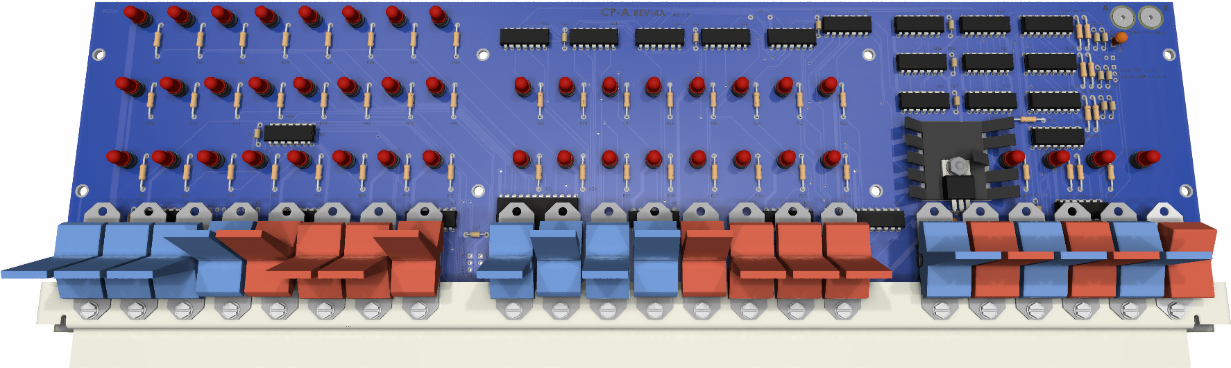
Our PCB uses a black silkscreen on a blue solder mask.
The blue and black completely disappear behind the red filter.
You may view the rendering of the PCB by clicking the links.
The back side of the PCB is is the same. Notice the power switch traces being routed farther from the sensitive circuitry. Because we preserved the original component placement, you can use the official IMSAI CP-A User Manual to assemble this kit.
Not that you would have to, as we provide a new User Manual similar to the IMSAI, but includes some of the “upgrades.”
Project Status
As of 24-April-2024, the project is underway. These are the tasks that have been completed:
- Established contact with the owner of a bare IMSAI CP-A Rev 4 PCB. We have reached an agreement for us to temporarily
take possession while we produce the CP-A Rev 4A. Upon completion, the original will be returned along with a new PCB.
- The owner of the bare IMSAI CP-A PCB will get the switch bracket reproduced.
- Drafting of the schematic, leaning on the original IMSAI CP-A schematic and the 2013 schematic by Josh Bensadon.
I have spotted several “new” IMSAI schematic and BOM errors.
Check out the CP-A support page for details.
- Thorough review (highlighting) of the schematic and the two references. The schematic met final approval when conflicting portions of the two reference schematic with a “virtual ring-out” of the reference PCB scans.
- Rough layout of the PCB according to the best sources I have.
- A rough auto-route to check for clearance and other problems. Decide on how to route power and ground. A final decision was made to match the original component placement as closely as possible. The only big change was the LED hole spacing which was changed to conform to the manufacturer’s specifications.
- Adjust the layout according to the precise measurements from the reference IMSAI CP-A Rev 4 PCB.
- Complete the IMSAI 8080 cabinet design capture including all sheet metal and front panel components.
- Do a final route and DRC.
- Create gerbers and fabrication package. Inspect and double-check measurements.
- Sourced the original IMSAI LEDs.
These tasks are in process:
- Work on a new CP-A User Manual. This will be ongoing during the development process.
What will be happening in the next few weeks is:
- Send out bids for the switch bracket fab to several fabricators.
- Produce prototype mechanical parts to build a complete IMSAI 8080 from scratch.
- Announce the availability of the board to the S-100 Computers group and determine interest and initial run.
- Send the board out for fabrication.
- Complete the new CP-A User Manual.
- Receive the prototype boards and inspect.
- Build and test one prototype. This will consume the metal switch bracket.
- In the unlikely event of a significant problem, fix it and go to step 5 or 6. Insignificant problems will be addressed with cuts and jumpers.
- Return the bare IMSAI CP-A board to its owner along with as many of the prototype boards they desire