IMSAI EXP-10

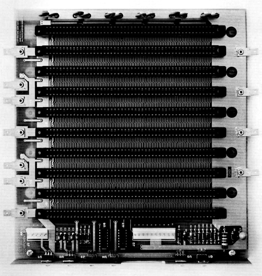
The EXP-10 is one of IMSAI’s last motherboards. It was used in the
PCS-80 line and the VDP-40 computers which were typically configured with an MPU-B, RAM-16/32/65, DIO,
and VIO boards. It was the first in the IMSAI line to feature active termination.
It was also the first to feature some active system integration features such as power supplies for the floppy disk drives and CRT monitor.
- Contents
Visit our Facebook group for announcements, discussions,
and more information about supporting the IMSAI EXP-10.
We put a lot of time into creating, gathering, and organizing the information in this page.
If you found any of this to be useful to you, especially if it helped you to make or save money,
please
to help us continue making content like this available.
Jumpers W1 and W2 control whether S-100 pins 20 and 70 are grounded. They are by default.
There are a few simple additions you will need to make the EXP-10 compliant. First is to connect bus pin 53 to ground.
Fortunately, it is not terminated. Then, bus pins 3, 54, and 55 need termination.
There are two spare resistors in the SIP packages but are too far away from pins 3, 54, and 55 to be useful and will have to be added as discrete resistors.
If you want to terminate the RESET (75) pin, there is a nearby spare resistor (see the section on RESET later to decide whether you really want to terminate RESET).
VI7* (11)
The EXP-10 drives this signal from a debounce circuit between J2-2 and J2-3. Grounding J2-3 makes VI7* go low (active).
When the interrupt is acknowledged by the system, or if J2-2 is grounded, VI7* goes high (inactive).
The problem with this is that VI7* is not driven by an open collector output. Instead it is driven by a totem-pole output.
The output drive is only −1.6/12mA.
If you do not need this behavior, we recommend cutting the trace going to the front 100-pin connector, pin 11.
If you do, you should still cut the trace, and wire up a 2.2kΩ ¼W resistor to U6-9 with the other end connecting to the base of a 2N3904 transistor.
The transistor’s emitter is connected to ground, and the collector to bus pin 11.
HLTA (48)
The EXP-10 drives an incandescent lamp from the HALT bus signal.
The problem is that the base current of the transistor is 9mA which is more than four times the spec.
The recommended fix is to replace Q3 with an NPN Darlington transistor, and increase R3 from 220Ω to 2.2kΩ.
RESET (75)
The MPU-A, MPU-B, and IFM all have an RC network on the signal line with a capacitor of several µF to ground.
It is important that this signal is not terminated unless it is driven low at power-up by other means.
This is because the terminator resistors will greatly reduce the RC time constant of the reset circuit.
The EXP-10 uses a 2.7V reference with 330Ω resistors to all the terminated lines. The EXP-10 predates the IEEE 696 standard — see the
IEEE 696 Compliance section for details.
Most other active termination systems that followed (and even to this date) use 270Ω resistors.
CompuPro introduced its line of active terminated motherboards using 560Ω resistors at each end of the bus,
providing approximately the same load as the 270Ω systems. Around 1982, they changed to a pair of 1.5kΩ resistors.
No one seems certain as to why.
If you decide to remove and replace the existing isolation resistors,
we strongly recommend a desoldering technique that preserves the board over the component being removed.
Hot air is almost never the correct tool to remove through-hole components.
It works well for surface mount because of the relatively small contact area with the pad.
The through hole contact area is much larger, making the heat required much higher.
Since you are probably not going to save the component anyway, the best course is to cut off the component’s leads and
remove them with traditional means.
Sometimes, the leads will just come out on the soldering iron tip through surface tension or magnetism;
otherwise, you can use a solder sucker or wick to clean out the holes.
The last thing you want to do is to damage the board.
Parts for the EXP-10 are coming soon, including replacement termination resistor arrays.
We put a lot of time into creating, gathering, and organizing the information in this page.
If you found any of this to be useful to you, especially if it helped you to make or save money,
please
to help us continue making content like this available.
Manuals
Schematic
The official IMSAI schematics for the EXP-10 could not be found. This schematic was drafted by Robert Weatherford from the IMSAI Development System owned by Parastream.
|