Korg CX-3 (Gen 2) Support

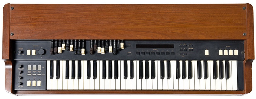
This is Korg’s second generation of the CX-3 organ. Unlike its predecessor, this CX-3 is digital and has far more capabilities.
It is distinguishable from the first-generation CX-3 because its drawbars are across the top of the manual as opposed to the analog drawbars to the left.
This keyboard is known by several aliases, digital CX-3, CX-3 v2, CX-3.2, and CX-3.22.
This page covers Korg CX-3 repair and Korg CX-3 parts.
Visit our Facebook group for announcements, discussions, and more information about supporting the Korg CX-3.
We put a lot of time into creating, gathering, and organizing the information in this page.
If you found any of this to be useful to you, especially if it helped you to make or save money,
please
to help us continue making content like this available.
Repair Services
For most repair situations, our service is a mail-in repair of one or more circuit boards inside the organ.
This is to get around the very expensive round-trip shipping that would otherwise be required.
Typically, we work with your local technician. Sometimes, all your technician needs is a little direction from us.
In other cases, they can remove the circuit board(s), send them to us, and replace them once they are returned from us.
If you are comfortable opening up the organ, you can act as your own technician.
Check out our videos to see how easy it is to send us the main board and put it back in when we return it to you.
If you would like for us to service the whole organ, you will need to arrange it with one of our service technicians using the
Support request form.
The following services are for individual circuit boards inside the CX-3, and include return shipping.
If your organ doesn’t power on at all and has a blank display, it’s probably the KLM-2090 (Power Supply).
Most other problems are usually in the KLM-2168 (Main Board).
If you’re not certain what’s wrong, use the Support request form and we will help you.
The most common approach is to purchase a circuit board repair service for each of the circuit boards you’d like us to repair.
These services will get your circuit boards into our shop and then back to you when they are diagnosed or repaired.
This includes the initial checkout, diagnostic, and report, as well as final testing of any repairs.
Once you make your service purchases, carefully pack the circuit board(s) and send the box to the address in the Contact Us page.
Check the videos for help with disassembly and packing.
When we receive your shipping box, you will receive an email with an estimated starting date for your job.
Repair services are performed in the order in which your shipping box arrives.
NOTE: If we do not receive your shipping box with 30 days, we will attempt to remind you to please send in your circuit board.
If we do not receive it in 90 days, we will issue a refund for the purchase.
After we receive your circuit board and perform the initial evaluation, you’ll receive an estimate for what we believe it will take to repair it.
We work hard to catch every problem in the estimate, and we are successful in the vast majority of cases.
The main board is a very complex circuit containing six microprocessors.
Because of this complexity, there may be other problems hiding behind what we found in the initial estimate.
NOTE: The estimate is good for 30 calendar days.
If you do not respond within 30 days, we will make multiple attempts to contact you through all means you disclose to us (email, phone, etc.).
If we still cannot reach you after an additional 15 calendar days, we will return your circuit boards to you.
If you choose to proceed, go to our website and order the services specified in the estimate.
When we receive the order and payment, we will place your repair order in the queue for repair.
Once the repairs have been performed and have passed all tests, the circuit board will be carefully packed and shipped back to you.
Although exceedingly rare, the post-repair testing may find additional problems that need to be addressed.
This situation can go one of two ways.
- Hopefully, we can identify what we believe will fix the circuit boards and give you a new estimate.
If you decide to proceed with another round, order the indicated services.
If you decide not to invest further in the organ, we understand.
We can either return your circuit board as it is, or refund the shipping portion of your initial repair purchase to you and we retain the board.
- Although this has never happened so far, we could find a problem so severe that it becomes impossible for us to do a proper repair.
In this case, we can either return your circuit board as it is, or refund the shipping portion of your initial repair purchase and we retain the board.
We would prefer to keep our perfect repair record if it is at all possible!
If you are purchasing parts or other items along with repair services, they will be shipped in the same box with the circuit board when the repair services are complete.
This is done to minimize shipping charges.
If you would like the parts to be shipped to you separately, please place them on a separate order.
These are the services we offer:
KLM-2168 (Main Board)
Please note that we do not have replacement KLM-2168 main boards for sale. Korg’s inventory of these boards dried up by 2010 and they are nowhere to be found. You must have a previously working KLM-2168 for us to be able to help you.
Begin by purchasing the Korg KLM-2168 Circuit Board Repair.
This gets your main board into our shop and then back to you when it is repaired.
This includes the initial checkout and report, as well as final testing of any repairs.
After we receive your main board and perform the initial evaluation, you’ll receive an estimate for any additional services needed for repair.
In most cases, the estimate will be one or more of the additional services listed here;
otherwise, it will be a fixed cost for parts and labor.
We work hard to catch every problem in the estimate, and we are successful in the vast majority of cases.
Due to the complex nature of the circuitry in the organ, there may be other problems hiding behind what we found in the initial estimate.
IMPORTANT: Please read the Repair Services section above and make sure you fully
understand show the repair services work before placing an order.
If you have any questions, use the Support request form and we will do our best to answer them.
FAQ
- Will my saved programs get wiped out?
- You should assume so. We will set the repaired main board to factory settings when the repairs require it. You should document any programs you want to save before sending us your main board.
KLM-2090 (Power Supply)
Begin by purchasing the Korg KLM-2090 Circuit Board Repair.
This gets your power supply into our shop and back to you when it is repaired.
This includes the initial checkout and report, as well as final testing of any repairs.
After we receive your power supply and perform the initial evaluation, you’ll receive an estimate for any additional items needed for repair.
In most cases, the estimate will be one or more of the additional services listed here;
otherwise, it will be a fixed cost for parts and labor.
IMPORTANT: Please read the Repair Services section above and make sure you fully
understand how the repair services work before placing an order.
If you have any questions, use the Support request form
and we will do our best to answer them.
Display Module
Replaces the fuse on the display module. This is the only repair we can do on the vacuum fluorescent display module. This gets your display module into our shop and then back to you when it is repaired.
Services not described here may be available on an add-on or time and materials basis. Use the Support request form to inquire.
Upgrades
If you have an early model CX-3, you have the option of upgrading it to a “Version 2” CX-3. The version 2 CX-3 resulted from the developing the BX-3 and improved many aspects of the instrument.
Details of the changes may be read here − In addition to these features, the overall sound in version 2 is cleaner without the low frequency noise that is sometimes present in version 1, which can get annoying when the rotary effect is on. It is a highly recommended upgrade.
If you are not sure if your CX-3 is a version 2, switch off the organ’s power. Hold down the DISPLAY key while switching the power back on.
Continue to hold the DISPLAY button until you see Main 2.01 Sub 1.00 on the display.
If it looks something like M01070501 S00111400 instead, it is not version 2 and could benefit from the upgrade.
There are three ways to upgrade an early model CX-3 that are described after the FAQ.
FAQ
- Will the upgrade wipe out my saved programs?
- Yes, it definitely will. You should document any programs you want to save before performing the upgrade. If you choose to perform the upgrade yourself, you will probably have to perform a factory reset by holding down the PROGRAM 2 and PROGRAM 7 buttons while switching on the power.
- Will the upgraded firmware support a pedal board?
- Just like the BX-3, the CX-3 V2 does not support a pedal board through MIDI. To the best of our knowledge, the first 12 (lowest octave) tones are missing from the digital tone generator, so even if using a MIDI pedal board was possible, the bass tones would be weak at best.
Firmware
Upgrade Service
The simplest and least expensive way to upgrade the firmware is to use the Korg KLM-2168 Circuit Board Firmware Upgrade to V2 Service (07-01000500) under Repair Services. We use the official Korg updater application on our custom MIDI upgrade rig. We guarantee this service. In the unlikely event that the updater application fails, we will replace the firmware chips at no extra charge.
After the upgrade, your organ will perform just as a version 2 CX-3 from the factory. The only minor exception is in Test Mode where Main ROM Test Error and Sub Code Test Error will display in units upgraded from Version 1 to Version 2. These messages are usually benign and do not actually indicate an error.
Owner Firmware Upgrade
You may upgrade the firmware yourself if you have an old PC with a MIDI interface.
Korg released a Windows application in 2003 that updated the firmware through a PC MIDI interface.
You may download the application here. You should be aware that the updater was built for Windows 2000 and Windows XP.
There is no guarantee it will run on anything else. Most modern PCs do not have MIDI ports, and most USB to MIDI converters do not handle the required SysEx MIDI messages well enough for the updater to function properly.
If the updater fails during the update, you could brick the organ.[1] Because the updater application caused so many problems, Korg Canada pulled it from their website. Korg USA kept it due to overwhelming demand at the time.
We recommend using our CX-3 firmware Upgrade Service which uses our custom MIDI upgrade rig. This service is guaranteed to work, even if we have to replace the firmware chips.
After the upgrade, your organ will perform just as a version 2 CX-3 from the factory. The only minor exception is in Test Mode where Main ROM Test Error and Sub Code Test Error will display in units upgraded from Version 1 to Version 2. These messages are usually benign and do not actually indicate an error.
Footnotes
1. A “bricked” organ will be non-functional and will have to be restored by replacing the two firmware chips.
Firmware Chip Replacement
Replacing the firmware chips should only be done if the organ cannot boot due to bad firmware, or if you do not want to use the firmware Upgrade Service.
A new pair of firmware chips may be purchased to replace the original ones in the main board. Replacing the chips is an advanced skill level job, requiring desoldering and replacing two 44-pin SOIC parts. You may perform the replacement yourself by ordering the Firmware Kit. If we are already working on your main board, you may ask us to do the replacement for you by including ordering the Kit and the Labor service. After the upgrade, your organ will perform just as a version 2 CX-3 from the factory. If you choose to perform the upgrade yourself, you will probably have to perform a factory reset by holding down the PROGRAM 2 and PROGRAM 7 buttons while switching on the power.
Parts
You may purchase many replacement parts for your CX-3. At this time, we do not have mechanical parts such as knobs and keys.
KLM-2090 (Power Supply) Electrolytic Capacitor Kit
This kit contains all 8 aluminum electrolytic capacitors for the power supply. The kit comes with a color-coded circuit board layout and color-coded bags of capacitors.
If you’re an average electronics DYIer, you can install this kit. Every capacitor meets or exceeds the original factory specifications.
We do not recommend replacing the KLM-2090 electrolytic capacitors unless you know there is a problem with one or more of them.
The KLM-2090 is built with long life capacitors, rated from 3,000 to 6,000 hours at 105°C. For the layperson, this translates to 60 to 120 years running 8 hours a day at temperatures under 45°C (113°F).
Frankly, other components are likely to fail first. Aside from failures or storage of the organ for prolonged periods at high temperatures, these capacitors should not wear out.
KLM-2168 Phone Jack Kit
Contains five replacement ¼" (6.35mm) jacks for the KLM-2168 board. If you’re an average electronics DYIer, you can install this kit. Here’s an interesting piece of trivia about these jacks –
in 2016, the manufacturer switched from silver plating to tin plating to reduce costs. By the way, manufacturers of similar products had already done this.
This silver oxidation is probably why so many phone jacks look so bad. We recommend replacing the jacks as a last resort after all other rehabilitation efforts such as cleaning have failed.
Korg BX-3/CX-3 Firmware Flash Chips
Contains two flash chips programmed with the latest available firmware from Korg. When you place an order, the chips are dried per J-STD-033B to avoid moisture-related failures during reflow and then programmed to maximize their data retention. This is an advanced skill level job, requiring desoldering and replacing two 44-pin SOIC parts. When we perform this repair, we use a SOIC-44 hot air station nozzle.
Miscellaneous Repair Parts
Many repair parts that are unusual or hard to find are listed here. If you can’t find what you need, ask us!
| Description | Part Number | Availability | Unit Price (USD) | Quantity | Ordering |
| Capacitor, 10µF ±20%, 25V, Aluminum Electrolytic, General Purpose, SMD, Extended Life | 32-10022874 | 10 day lead time | $1.50 | | |
| Transistor, Bipolar PNP, 2SA812 M5, SOT (Small-Outline Transistor Package) | 34-01081230 | 10 day lead time | $1.50 | | |
| IC, 74HCU04, Hex Inverter, SOP (EIAJ Type II, 1.27mm Pitch, 5.3mm Wide) | 36-13300415 | 1 in stock, more in 10 days | $3.37 | | |
| IC, 74HC05, Hex Inverter with Open-Drain Outputs, SOP (EIAJ Type II, 1.27mm Pitch, 5.3mm Wide) | 36-28000515 | 1 in stock, more in 10 days | $3.39 | | |
| IC, 74HC4040, 12-Stage Binary Ripple Counter, SOP (EIAJ Type II, 1.27mm Pitch, 5.3mm Wide) | 36-28104015 | 1 in stock, more in 10 days | $4.01 | | |
| IC, 74HC4052, Dual 4-Channel Analog Multiplexer/Demultiplexer, SOP (EIAJ Type II, 1.27mm Pitch, 5.3mm Wide) | 36-28105215 | 1 in stock, more in 10 days | $3.60 | | |
| IC, 29EE010-90, 5V 1Mbit (128K×8) Page-Write EEPROM PLCC-32 | 37-29301009 | 30 day lead time | $12.00 | | |
| IC, Em614163A-50, 256K x 16 High Speed EDO DRAM, SOJ-40 | 37-61416350 | In stock | $6.00 | | |
| IC, M5216, Dual Large-Current Operational Amplifiers, SOIC (4.4mm to 5.0mm Wide) | 38-20521621 | 10 day lead time | $2.50 | | |
| IC, M5218, Dual Low-Noise Operational Amplifiers, SOIC (4.4mm to 5.0mm Wide) | 38-20521821 | In stock | $1.50 | | |
| IC, Texas Instruments TMS57070FFT DSP, QFP-100 (New Old Stock) | 39-06057070 | 3 in stock, more in 30 days | $156.00 | | |
| IC, Burr-Brown PC1716E, SoundPlus 24-Bit 96kHz Sampling CMOS Delta-Sigma Digital/Analog Converter, SSOP-28 (New Old Stock) | 39-10001716 | In stock | $10.50 | | |
| IC, Hitachi H8S/2352 / HD6412352F20 16-Bit µP, 2-20MHz, 8K RAM, QFP-128 (New Old Stock) | 39-11023520 | In stock | $84.00 | | |
| Fuse, 750 mA, 125VAC Ceramic Fast Blow 2410 SMD | 52-75030109 | In stock | $1.50 | | |
All the above parts are for the KLM-2168 (main board) except the fuse, which is for the vacuum fluorescent display board.
- s01e001: How to remove the power supply from a Korg CX-3 Gen 2
- s01e002: How to remove the main board from a Korg CX-3 Gen 2
- s01e004: How to replace the power supply from a Korg CX 3 Gen 2
- s01e005: How to replace the main board from a Korg CX-3 Gen 2
Check out our YouTube channel for more videos!
We put a lot of time into creating, gathering, and organizing the information in this page.
If you found any of this to be useful to you, especially if it helped you to make or save money,
please
to help us continue making content like this available.
DYI Repairs
If you have good soldering and desoldering tools and skills, you may want to consider doing some repairs yourself and save labor cost and time.
Replacing Tact Switches
Are some of the panel buttons not working reliably? Do you have to press them repeatedly to get them to work? You might want to consider replacing the tact switches.
There are 34 of them in the CX-3. These tact switches are susceptible to dust, smoke, and other contaminants. We used to offer services for the tact switches, but it didn’t sell well. We suspect that our reference organ was subjected to one or more liquid spill episodes, causing them to be unreliable. Most organs do not seem to have this problem.
If you want to replace some of the tact switches on your organ, we have good and bad news. The good news is that we have the exact part number for the switch used by Korg, and even an upgraded part which we used to offer that has 10 times the rated lifespan. The bad news is that the manufacturer discontinued the parts in 2020, and they may be difficult to find. The original switch is a Panasonic EVQ11A09K, and the upgraded part is EVQ11D09K. They are identical in all mechanical and electrical specs except the ’D09K has 10 times the rated lifespan. There are other variants with different actuation forces, but are otherwise compatible.
While this will take a while to disassemble the organ, replace the switches, and reassemble the organ, it will make it operate like new.
To prolong the life of your new switches, we recommend keeping the organ under a dust cover when not in use.
Replacing Phone Jacks
The ¼-inch phone jacks can get corroded or worn out. If you are experiencing scratchy or intermittent operation plugging in cords into the phone jacks, try cleaning them with DeoxIt first.
DO NOT Spray directly into the jacks! Instead, saturate a swab and insert it into the jack. Move the swab in and out a few times and try to reach toward the top of the jacks where the contacts are.
If this does not fix the problem, the jacks must be replaced.
You may purchase the jacks from us here, or from another supplier. This operation will require a slightly higher skill level than replacing the tact switches, as the printed circuit board is two-sided.
You may find some helpful videos here.
Replacing the Firmware Chips
While this is not a common repair, replacing the firmware chips may be necessary in the following situations:
- You have a CX-3 and you want to upgrade it to Version 2 yourself without using the Korg-supplied upgrade application (see Upgrades).
- You used the Korg-supplied upgrade application and it failed, “bricking” the organ.
- You have determined that the firmware has degraded due to “bit rot” or other problems preventing the organ from booting.
You may purchase the set of firmware chips from us here. The firmware chips are programmed after you order them and have not been sitting on a shelf for years.
This is an advanced skill level job, requiring desoldering and replacing two 44-pin SOIC parts. When we perform this repair, we use a special nozzle for SOIC-44 with our hot air station to remove the old chips.
Manuals
IC Datasheets
The Motorola DSP56362 is used as a tone generator and keying matrix processor in the KLM-2168. This chip is no longer in production. Because of its early reliability problems, we have decided to publish some of our research into this part here. This article may help you find your own parts on what we call the “EOL Market,” and how to avoid risky parts.
The TMS57070 chip (used in the KLM-2168) was a rather short-lived DSP from Texas Instruments that ran from 1995 through 2000. The CX-3 uses two of these chips to create the vibrato/chorus, rotary effect (Leslie), reverb, and mixes in the percussion signal from the tone generator post-vibrato/chorus. There is no official information about this DSP from Texas Instruments, but a very clever fellow has taken on the project of reverse-engineering the part. You can see his work at GitHub - Prehistoricman/TMS57070: Tools & docs for the TI DSP TMS57070 including disassembler.
General Information
You may access useful information for debugging and determining what version of the firmware your organ has. Refer to the following table as a guide, and hold down the indicated buttons while switching on the power.
Be patient. You have to hold the buttons down until the desired information displays.
- PROGRAM 1 and PROGRAM 8
- Displays the loader firmware version. It is normally displays Ipl V2.00 000422AB. This is the original loader version and never changed throughout the production of the CX-3.
- PROGRAM 2 and PROGRAM 7
- Perform a factory reset. Displays Load Factory Data? , Press the WRITE/ENTER button to completely refresh the unit to factory condition.
- PROGRAM 4 and PROGRAM 6
- Enter the Test Mode. See Test Mode for details.
- DISPLAY
- Displays the master and subsystem CPU firmware versions. The last V1 versions are M01070501 S00111400. The last V2 versions are Main 2.01 Sub 1.00 . Previous V1 versions include
M00090200 S00090100.
Test Mode
The test mode
begins by testing the internal components of the organ, and then moving into interactive tests of the keys, buttons, and lights. If you have a MIDI cable, connect it from the IN jack to the OUT jack for the MIDI loop test.
If you don’t have a cable, you can skip the test when it reports an error.
During test mode, use the following percussion buttons to navigate:
| ON |
Go to the previous item marked with a ✔. |
| SOFT |
Go to the next item marked with a ✔. |
| FAST |
Go to the previous step. |
| 3rd |
Go to the next step, or skip an internal test error. |
The test mode differs between Version 1 and Version 2.
Version 1 Test Mode
| Item |
Display |
Description |
| |
M01070501 S00111400 |
The main and sub-MPU versions. Yout actual version numbers may vary. Smaller magnitude numbers indicate older firmware. |
| ✔ |
Internal Testing ... |
|
| |
Main CPU Testing ... |
Main CPU RAM Error indicates a failure. |
| |
Main Code Testing... |
Tests the firmware in the main MPU (IC18). Main Code Error indicates a failure. |
| |
Main Flash Testing.. |
Checks the integrity of the settings in the user flash chip (IC22). |
| |
FPS com Testing ... |
Tests the serial communications lines between the main board and the front panel MPU. FPS Test Error indicates a failure. |
| ✔ |
Sub Code Testing ... |
Tests the firmware in the sub-MPU (IC6). Sub Code Error indicates a failure. |
| ✔ |
Sub RAM Testing ... |
Tests the DRAM used by the FX DSPs (IC24, IC25). Sub RAM Error indicates a failure. |
| ✔ |
Sub-DSP Testing ... |
Preliminary tests for the four DSP chips. Sub‑DSP Error indicates a failure. |
| |
Sub-DSP Test1 ... |
Tests the TG-B DSP (IC8) block. DSP1 Test Failed indicates a failure. If IC7 is a 1J21D mask chip, it is recommended to replace it also because of the history of failure with these chips. |
| |
Sub-DSP Test2 ... |
Tests the TG-A DSP (IC7) block. DSP2 Test Failed indicates a failure. If IC8 is a 1J21D mask chip, it is recommended to replace it also because of the history of failure with these chips. |
| |
Sub-DSP Test3 ... |
Tests the EFX DSP-A (IC19) block. DSP3 Test Failed indicates a failure with the DSP-A chip (IC19) or its DRAM (IC24). |
| |
Sub-DSP Test4 ... |
Tests the EFX DSP-B (IC20) block. DSP4 Test Failed indicates a failure with the DSP-B chip (IC20) or its DRAM (IC25). |
| ✔ |
MIDI Loop Testing... |
Tests the MIDI IN and OUT loop-back.
Displays MIDI Loop Error and pauses if there is no MIDI cable between the MIDI IN and OUT jacks, or if there is actually an error.
Press SOFT to advance from pause. There is no way to test MIDI THRU. |
| ✔ |
Switch Testing |
Press 3rd to begin switch tests or SOFT to skip. During switch testing, the organ will emit a short tone if the incorrect key is pressed. |
| ✔ |
████████████████████ |
Illuminates all display character pixels for examination. In older organs, you may see some burn-in. Press 3rd or SOFT to advance. |
| |
|
Darkens all display character pixels for examination. Press 3rd to advance. |
| ✔ |
Expression Vol: |
Turn the EXPRESSION / OVERDRIVE knob full counterclockwise. The displayed value should be 0. Turn the knob full clockwise. The displayed value should be 127.
Advances to the next step when turned full counterclockwise. |
| |
Treble Vol: |
Turn the TREBLE knob from full counterclockwise. The displayed value should be 0. Turn the knob clockwise to the center detent. The displayed value should be 64.
Turn the knob full clockwise. The displayed value should be 127. Advances to the next step when turned full counterclockwise. |
| |
Bass Vol: |
Turn the BASS knob from full counterclockwise. The displayed value should be 0. Turn the knob clockwise to the center detent. The displayed value should be 64.
Turn the knob full clockwise. The displayed value should be 127. Advances to the next step when turned full counterclockwise. |
| |
Reverb Vol: |
Turn the REVERB OFFSET knob from full counterclockwise. The displayed value should be 0. Turn the knob clockwise to the center detent. The displayed value should be 64.
Turn the knob full clockwise. The displayed value should be 127. Advances to the next step when turned full counterclockwise. |
| ✔ |
█ <> |
Drawbar test. For each drawbar from left to right, push it all the way in, then slowly all the way out, while observing the animated display.
The animated drawbar should accurately show the drawbar position. Push the drawbar all the way in to advance to the next drawbar. |
| ✔ |
V/C Encoder |
The display prompt to begin testing the VIBRATO / CHORUS knob. Press 3rd to begin the tests or SOFT to skip. |
| |
V/C Encoder 0 |
Turn the knob and observe that the display value ranges from -128 to 127. Press 3rd to advance. |
| |
V/C Encoder R:0 |
Turn the knob exactly one revolution clockwise. The display should range from 0 to 15 with a < displayed in the rightmost character position. Press 3rd to advance. |
| |
V/C Encoder L:0 |
Turn the knob exactly one revolution counterclockwise. The display should range from 0 to -15 with a < displayed in the rightmost character position. Press 3rd to advance. |
| ✔ |
Pedal Test 1: |
Setup: Plug a foot switch into PEDAL 1 jack. Plug a generic expression pedal into the PEDAL 2 jack.
Plug in a Korg CX-3 expression or equivalent such as a FC7 Volume Pedal into the EXPRESSION PEDAL jack. Press FAST if the display has advanced to Pedal Test 2.
Run through the 6 tests in this item. At the end when the Keyboard Test Wait.. message is displayed, plug the three cables back into the jacks, but swap PEDAL 1 and PEDAL 2.
This will verify that both ASSIGNABLE PEDAL inputs can take an expression or volume pedal, and a foot switch.
Press and hold the switch and observe the value is 127. Release the switch and observe the display has advanced to the next step. |
| |
Pedal Test 2: |
Move the generic expression pedal to its lowest volume position. Rock it forward and then back all the way. Observe the display value is 0.
Move the pedal to the loudest position and observe the display is 127. Move it to the lowest volume position to advance to the next step. |
| |
Pedal Test 3: |
Move the expression pedal to its lowest volume position. Rock it forward and then back all the way. Observe the display value is 0.
Move the pedal to the loudest position and observe the display is 127. Move it to the lowest volume position to advance to the next step. |
| |
Remove Pedal1 |
Unplug the cord in the PEDAL 1 jack and observe the display has advanced to the next step. |
| |
Remove Pedal2: |
Unplug the cord in the PEDAL 2 jack and observe the display has advanced to the next step. |
| |
Remove Pedal3: |
Unplug the cord in the EXPRESSION PEDAL jack and observe the display has advanced to the next step. |
| ✔ |
Keyboard Test Wait.. |
Press each playing key as indicated by the display. You will have to strike the key with some force to advance to the next key. |
| ✔ |
Output Level Test1 |
1 kHz in the left channel, 415 Hz in the right at 0 dB. |
| |
Output Level Test2 |
490 Hz in the left channel, 1 kHz in the right at 0 dB. |
| |
Output Level Test3 |
1 kHz in the left channel, 612 Hz in the right at -6 dB. |
| |
Output Level Test4 |
550 Hz in the left channel, 1 kHz in the right at -6 dB. |
| ✔ |
Noise Test 1 |
? |
| |
Noise Test 2 |
? |
| |
Noise Test 3 |
? |
| |
Noise Test 4 |
? |
| ✔ |
Load Preset Programs |
This is the last prompt of test mode. |
Version 2 Test Mode
| Item |
Display |
Description |
| |
Main 2.01 Sub 1.00 |
The main and sub-MPU versions. |
| ✔ |
Main RAM Test |
Tests the RAM in the main MPU. Main RAM Test Error indicates a failure. |
| |
Main ROM Test |
Tests the firmware in the main MPU (IC18). It is common for Main ROM Test Error to display in units upgraded from Version 1 to Version 2. |
| |
Flash ROM Test |
Checks the integrity of the setting in the user flash chip (IC22). |
| |
FPS Com Test |
Tests the serial communications lines between the main board and the front panel MPU. |
| ✔ |
Sub Code Test |
Tests the firmware in the sub-MPU (IC6). It is common for Sub Code Test Error to display in units upgraded from Version 1 to Version 2. |
| ✔ |
Sub RAM Test |
Tests the DRAM used by the FX DSPs (IC24, IC25). Sub RAM Test Error indicates a failure. |
| ✔ |
DSP Test |
Preliminary tests for the four DSP chips. |
| |
DSP1 Test |
Tests the TG-B DSP (IC8) block. DSP1 Test Error indicates a failure. If IC7 is a 1J21D mask chip, it is recommended to replace it also because of the history of failure with these chips. |
| |
DSP2 Test |
Tests the TG-A DSP (IC7) block. DSP2 Test Error indicates a failure. If IC8 is a 1J21D mask chip, it is recommended to replace it also because of the history of failure with these chips. |
| |
DSP3 Test |
Tests the EFX DSP-A (IC19) block. DSP3 Test Error indicates a failure with the DSP-A chip (IC19) or its DRAM (IC24). |
| |
DSP4 Test |
Tests the EFX DSP-B (IC20) block. DSP4 Test Error indicates a failure with the DSP-B chip (IC20) or its DRAM (IC25). |
| ✔ |
MIDI Loop Test |
Tests the MIDI IN and OUT loop-back.
Displays MIDI Loop Error and pauses if there is no MIDI cable between the MIDI IN and OUT jacks, or if there is actually an error. Press SOFT to advance from pause. There is no way to test MIDI THRU. |
| ✔ |
Switch LED Test |
Press 3rd to begin switch tests or SOFT to skip. During switch testing, the organ will emit a short tone if the incorrect key is pressed. |
| ✔ |
████████████████████ |
Illuminates all display character pixels for examination. In older organs, you may see some burn-in. Press 3rd or SOFT to advance. |
| |
|
Darkens all display character pixels for examination. Press 3rd to advance. |
| ✔ |
ExpressTurnRight 0 |
Turn the EXPRESSION / OVERDRIVE knob full counterclockwise. The displayed value should be 0. Turn the knob full clockwise. The displayed value should increment toward 127.
Advances to the next step when turned full clockwise. |
| |
ExpressTurn Left 127 |
Turn the EXPRESSION / OVERDRIVE knob full counterclockwise. The displayed value should decrement toward 0.
Advances to the next step when turned full counterclockwise. |
| |
Treble TurnRight 0 |
Turn the TREBLE knob full counterclockwise. The displayed value should be 0. Turn the knob clockwise to the center detent.
The displayed value should be 64. Turn the knob full clockwise. The displayed value should increment toward 127. Advances to the next step when turned full clockwise. |
| |
Treble Turn Left 127 |
Turn the TREBLE knob full counterclockwise. The displayed value should decrement toward 0. Advances to the next step when turned full clockwise. |
| |
Bass TurnRight 0 |
Turn the BASS knob from full counterclockwise. The displayed value should be 0. Turn the knob clockwise to the center detent.
The displayed value should be 64. Turn the knob full clockwise. The displayed value should increment toward 127. Advances to the next step when turned full clockwise. |
| |
Bass Turn Left 127 |
Turn the BASS knob full counterclockwise. The displayed value should decrement toward 0. Advances to the next step when turned full clockwise. |
| |
Reverb TurnRight 0 |
Turn the REVERB OFFSET knob full counterclockwise. The displayed value should be 0. Turn the knob clockwise to the center detent.
The displayed value should be 64. Turn the knob full clockwise. The displayed value should increment toward 127. Advances to the next step when turned full clockwise. |
| |
Reverb Turn Left 127 |
Turn the REVERB OFFSET knob full counterclockwise. The displayed value should decrement toward 0. Advances to the next step when turned full clockwise. |
| ✔ |
█ <> |
Drawbar test. For each drawbar from left to right, push it all the way in, then slowly all the way out, while observing the animated display.
The animated drawbar should accurately show the drawbar position. Push the drawbar all the way in to advance to the next drawbar. |
| ✔ |
Encoder Test |
The display prompt to begin testing the VIBRATO / CHORUS knob. Press 3rd to begin the tests or SOFT to skip. |
| |
Encoder |
Turn the knob and observe that the display value ranges from -128 to 127. Press 3rd to advance. |
| |
Encoder Right 0 |
Turn the knob exactly one revolution clockwise. The display should range from 0 to 15 with a < displayed in the rightmost character position. Press 3rd to advance. |
| |
Encoder Left 0 |
Turn the knob exactly one revolution counterclockwise. The display should range from 0 to -15 with a < displayed in the rightmost character position. Press 3rd to advance. |
| ✔ |
Pedal1 Test |
Setup: Plug a foot switch into PEDAL 1 jack. Plug a generic expression pedal into the PEDAL 2 jack.
Plug in a Korg CX-3 expression or equivalent such as a FC7 Volume Pedal into the EXPRESSION PEDAL jack. Press FAST if the display has advanced to Pedal Test 2.
Run through the 6 tests in this item. At the end when the Keyboard Test message is displayed, plug the three cables back into the jacks, but swap PEDAL 1 and PEDAL 2.
This will verify that both ASSIGNABLE PEDAL inputs can take an expression or volume pedal, and a foot switch.
Press and hold the switch and observe the value is 127. Release the switch and observe the display has advanced to the next step. |
| |
Pedal2 Test |
Move the generic expression pedal to its lowest volume position. Rock it forward and then back all the way. Observe the display value is 0.
Move the pedal to the loudest position and observe the display is 127. Move it to the lowest volume position to advance to the next step. |
| |
Pedal3 Test |
Move the expression pedal to its lowest volume position. Rock it forward and then back all the way. Observe the display value is 0.
Move the pedal to the loudest position and observe the display is 127. Move it to the lowest volume position to advance to the next step. |
| |
Remove Pedal1 |
Unplug the cord in the PEDAL 1 jack and observe the display has advanced to the next step. |
|
Remove Pedal2 |
Unplug the cord in the PEDAL 2 jack and observe the display has advanced to the next step. |
| |
Remove Pedal3 |
Unplug the cord in the EXPRESSION PEDAL jack and observe the display has advanced to the next step. |
| ✔ |
Kbd CX C7 / C7 7F |
Press each playing key as indicated by the display. You will have to strike the key with some force to advance to the next key. |
| ✔ |
Output Level Test1 |
1 kHz in the left channel, 415 Hz in the right at 0 dB. |
| |
Output Level Test2 |
490 Hz in the left channel, 1 kHz in the right at 0 dB. |
| |
Output Level Test3 |
1 kHz in the left channel, 612 Hz in the right at -6 dB. |
|
Output Level Test4 |
550 Hz in the left channel, 1 kHz in the right at -6 dB. |
| ✔ |
Noise Test 1 |
? |
| |
Noise Test 2 |
? |
| |
Noise Test 3 |
? |
| |
Noise Test 4 |
? |
| ✔ |
Pre Load |
This is the last prompt of test mode. |
|