Korg BX-3/CX-3 Gen 1 Troubleshooting
This content was last updated on 30-July, 2021.
We put a lot of time into creating, gathering, and organizing the information in this page.
If you found any of this to be useful to you, especially if it helped you to make or save money,
please
to help us continue making content like this available.
This guide assumes you have the organ open on the bench with the large circuit (KLM-244) board exposed. On a CX-3, this will require unbolting the keyboard and moving it out of the way. It also assumes you have the schematic diagram handy. The page that led you here has helpful links to videos, manuals, schematics, and datasheets.
Here are some common symptoms and suggested ways to proceed.
- Organ Appears Dead
- Check line fuse, then check the power supply.
- No Sound with Functioning Control Switches
- Begin the troubleshooting with the KLM-244 circuit board.
If everything checks out, then move on to the KLM-245.
- No Key Click
- The lack of key click could be IC-3 on the KLM-244 circuit board, or it could be in the KLM-245.
- No Percussion
- The lack of percussion could be IC-5 on the KLM-244 circuit board, or it could be in the KLM-245.
- Missing Octaves In One Or More Drawbars
- This is almost always in the KLM-244 circuit board.
KLM-244 Circuit Board
The KLM-244 is the large circuit board behind the keyboard assembly. Begin with a visual inspection of R64.
It is located at the very back near two small connectors.
It is a 10Ω isolation resistor and can act as a fuse if one the SM304A or SM305A/B ICs (IC-1 through IC-5) goes bad.
If it is charred, it may still work, but is a clear indication that there is something wrong with one or more of these ICs.
Theory of Operation
The KLM-244 is responsible for converting the 61 keyboard keypress signals into 9 analog outputs which correspond to the tones sent to each of the drawbars.
Keyboard Encoder and Tone Generator ICs
The tone generation starts with a roughly 2 MHz clock generated by Q4 and Q5, and buffered by Q6 and IC-6.
It is tuned by adjusting VR1 on the circuit board, as well as VR1 on the KLM-245 control board.
The clock is fed into IC-7 which divides it into the 12 top octave notes.
Each of the 12 signals is attenuated by a 12kΩ series resistor and a 5 volt zener diode such that the signals swing between 0
and 5 volts. These top octave signals are sent to the three tone generators, IC-3, IC-4, and IC-5 as the set of tone inputs.
 The tone generation system uses a 3-wire serial bus to transmit the keypress information to the tone generator ICs.
Otherwise, 61 keypress inputs would be needed for each of the tone generators.
With the serial interface, the tone generators easily fit into a 40-pin DIP.
The clock (T) and sync (U) signals are generated by one of the tone generator ICs (IC-3), R5, and C1.
The data (D) signal is generated by the keyboard encoder made up of IC-1 and IC-2.
These ICs are used as 32-bit parallel to serial shift registers together to make 65 bits
(the 65th bit is the serial input of the first SM304A).
The first 61 of these bits are used for the keys themselves.
The remaining 4 are used for footage programming not used by this circuit.
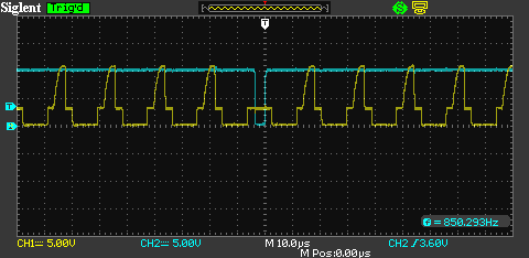
The scope trace to the right shows the clock signal in yellow and the sync signal in cyan.
The clock is approximately 55 kHz with approximately a 50% duty cycle.
The spike in the middle of the high portion is irrelevant to the system; it uses the approximately 3 volt swing.
The sync signal goes low every 65th clock cycle, giving it a period of about 132 ms.
Interestingly, the spike in the clock is suppressed during sync.
As you can see in the trace, the clock always swings with a 50% duty cycle at about a 3 volt amplitude.
The tone generation system uses a 3-wire serial bus to transmit the keypress information to the tone generator ICs.
Otherwise, 61 keypress inputs would be needed for each of the tone generators.
With the serial interface, the tone generators easily fit into a 40-pin DIP.
The clock (T) and sync (U) signals are generated by one of the tone generator ICs (IC-3), R5, and C1.
The data (D) signal is generated by the keyboard encoder made up of IC-1 and IC-2.
These ICs are used as 32-bit parallel to serial shift registers together to make 65 bits
(the 65th bit is the serial input of the first SM304A).
The first 61 of these bits are used for the keys themselves.
The remaining 4 are used for footage programming not used by this circuit.
The scope trace to the right shows the clock signal in yellow and the sync signal in cyan.
The clock is approximately 55 kHz with approximately a 50% duty cycle.
The spike in the middle of the high portion is irrelevant to the system; it uses the approximately 3 volt swing.
The sync signal goes low every 65th clock cycle, giving it a period of about 132 ms.
Interestingly, the spike in the clock is suppressed during sync.
As you can see in the trace, the clock always swings with a 50% duty cycle at about a 3 volt amplitude.
Q1, Q2, and Q3 act as emitter-follower buffers for the T, U, and D signals.
 The 61 keypress inputs are fed into IC-1 and IC-2, which act together as a 65-bit shift register.
The data are shifted on the falling edge of the clock.
When the sync signal occurs during a clock period, the parallel data from the keyboard are loaded into the shift register
on the next clock falling edge and the C5 (highest note on the keyboard) is presented on the D signal.
On subsequent clock falling edges, the D signal represents the next highest key position (high level = key down).
After the C1 key (lowest) is shifted onto the D signal, the next 3 clocks set D to low,
and the last one before the next sync is high. Then the process repeats.
With all keys up, the data stream should stay low except for the sync position.
The 61 keypress inputs are fed into IC-1 and IC-2, which act together as a 65-bit shift register.
The data are shifted on the falling edge of the clock.
When the sync signal occurs during a clock period, the parallel data from the keyboard are loaded into the shift register
on the next clock falling edge and the C5 (highest note on the keyboard) is presented on the D signal.
On subsequent clock falling edges, the D signal represents the next highest key position (high level = key down).
After the C1 key (lowest) is shifted onto the D signal, the next 3 clocks set D to low,
and the last one before the next sync is high. Then the process repeats.
With all keys up, the data stream should stay low except for the sync position.
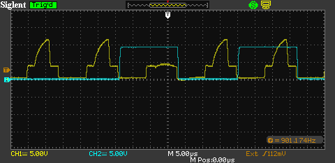
Looking at the trace to the right, the 65th bit is shown mostly to the left of the hash mark,
and is high because the SM304A parallel inputs are active low (key contact to ground),
and the IC-1 ES input is active high (positive logic).
The trace shown is from holding down the B5 (next to the rightmost key on the keyboard).
IC-3 and IC-4 are both SM305A, but generate a different set of drawbar signals because of the way the OS pin is connected.
IC-3 connects it to a 470kΩ resistor to +12V and a 47pF capacitor to ground.
This causes the SM305A to generate the clocks on the T and U pins, and to generate the tones for the
16', 5⅓', and 8' drawbars. This is called footage group 3.
It also instructs the SM305A to generate a 5µs negative pulse on the THKF pin,
which is stretched to 6.5ms by IC-8 (NE555) and used to generate the key-click noise.
The IC-4 OS pin is connected to ground which configures the T and U signals as inputs (slave mode),
and to generate the tones for the 4', 2⅔', 2', and 1⅓' drawbars. This is called footage group 1.
The SM305B (IC-5) generates the tones for the 1⅗' and 1' drawbars.
It also generates a high to low transition on the KD pin when the first key is pressed and returns high when all keys are
released. This signal is sent to the KLM-245 circuit board to create the percussion effect.
Filtering and Mixing
The drawbar signals are presented in octave groups on the tone generator ICs.
They are grouped in octaves because the tone generators can only output square waves.
Each drawbar is represented by five pins as each drawbar covers up to 5 octaves.
Each tone pin is filtered by a third-order active filter to change the octave of square waves into an octave of sine waves.
The five filters related to a drawbar are summed by an op-amp and available on the two 9-pin connectors on the back of the circuit board.
Some versions of the KLM-244 have trimmer pots on each drawbar mixer.
This allows for the fine-tuning of the level of each drawbar.
Troubleshooting
Always begin with a thorough visual inspection of the circuit board.
Be sure to do this on a static controlled workstation.
Check all electrolytic capacitors for signs of electrolyte leaking.
Green corrosion on the exposed lead, residue on the copper-side pad or trace etching are signs of leakage.
If you find signs of leakage, remove and replace all the electrolytic capacitors.
Be sure to remove as much of the corrosion as you can by scraping and isopropyl alcohol before installing the new ones.
Repair any damaged circuit board traces as necessary.
D6 through D14 near IC-5 are especially vulnerable to breakage.
Replace any broken zener diodes before attempting to power up the board. Any decent 5.2 volt zener will do.
Check R64 for charring.
If R64 looks burned, you will have to determine which of the Siemens ICs (IC-1 through IC-5) is shorting the power supply.
We’re going to remove IC-1 through IC-5.
If they are not in sockets, you should carefully unsolder them, clean the leads, and install sockets.
Check R46 with an ohmmeter.
If it is bad, replace it with a temporary resistor, because you will probably damage it when you re-install the Siemens ICs one at a time.
Hook up a voltmeter across R64 so you can see when the drop across it is more than a few millivolts.
This is when you immediately power off with at least one culprit.
For the specified ICs the following order, power-off the organ, install the IC, power-up the organ and check the drop across R64;
IC-3, IC-1, IC-2, IC-4, and IC-5. One or more of these ICs will draw too much current and cause an unsafe voltage drop across R64.
They must be replaced to proceed. Once the Siemens ICs have been re-seated in their sockets, replace R64 with a fresh 10Ω ¼W carbon resistor.
We will begin by looking for signals on the KLM-244 with the power on.
Check for top octave signals.
These signals may be easily probed in a group of jumpers to the left of IC-4, labeled by the musical notes they represent.
If any one of them is missing, the serial clock oscillator in IC-3 may not start.
It may not be the fault of IC-7; IC-3, IC-4, or IC-5 can short them out if they fail.
To be sure, remove IC-3, IC-4, and IC-5 and check the signals again.
If one or more of the signals is still missing, replace IC-7.
One at a time, replace IC-3, IC-4, and IC-5 to find out which ICs are interfering with the top octave signals and replace them.
Check for serial clock and data pulses.
IC-3 generates the approximately 55 kHz clock T.
It is buffered by an emitter-follower, which boosts the current-sourcing of the T signal.
By the way, the schematic incorrectly shows T being connected to +12V.
Check operation of the SM304As. Trigger the scope on the sync pulse and look at the data stream as you press keys.
Check the operation of the key click pulse on IC-3 pin 33. It should be high, and pulse low for 5µs every key press.
Check the operation of the percussion trigger pulse on IC-5 pin 33.
It should be high with a low transition when the first key is pressed and returns high when all keys are released.
|